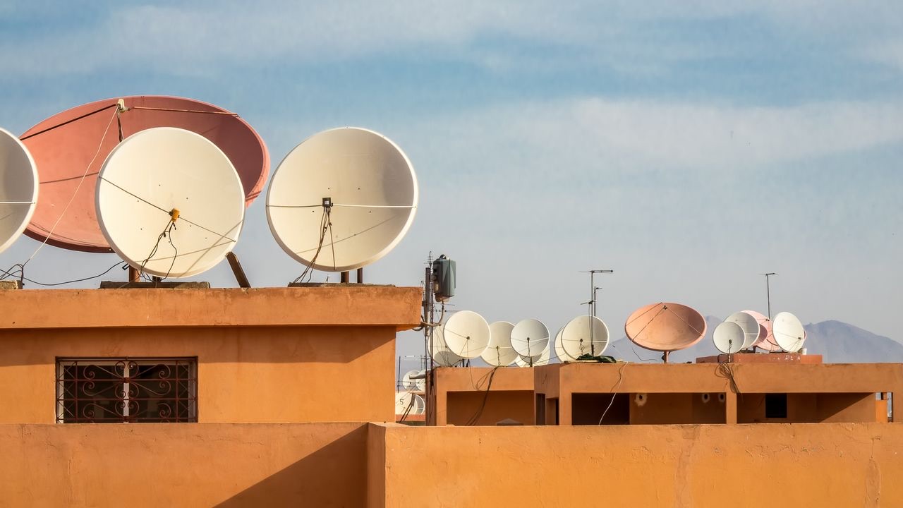
The super high frequency band — 3 GHz to 30 GHz — sits at an interesting boundary in antenna engineering. Below it, antennas are physically large relative to their applications, and propagation behaves predictably over terrestrial distances. Above it, the physics of millimeter-wave propagation introduce complications that most RF systems avoid. SHF is where the engineering gets genuinely demanding: wavelengths are short enough that precision manufacturing matters, atmospheric effects are significant enough to require link budget margins, and the applications — satellite communications, radar, microwave backhaul — place strict performance requirements on the antenna systems.
Understanding what makes SHF antennas different from their VHF and UHF counterparts starts with the physics of the frequency band itself.
Wavelength and antenna size at SHF
At 3 GHz, the free-space wavelength is approximately 10 centimeters. At 30 GHz, it’s 1 centimeter. These dimensions have direct consequences for antenna design. A parabolic reflector antenna intended to produce a 1-degree beamwidth at 10 GHz requires a dish diameter of roughly 1.7 meters. The same beamwidth at 3 GHz would require a dish about 5.7 meters in diameter. The relationship between aperture size, frequency, and beamwidth is linear — higher frequencies allow physically smaller apertures to achieve the same angular resolution.
This is one reason SHF is used for applications requiring high spatial precision. Satellite ground stations targeting a geostationary satellite at 35,786 km altitude need enough directional gain to close the link budget, and enough angular precision to track the satellite accurately. At SHF frequencies, achievable apertures are manageable in size while still producing the required gain and resolution. At VHF or UHF, the equivalent antennas would be impractically large.
Atmospheric effects: where SHF engineering gets complicated
The same frequency range that enables compact, high-gain antennas also encounters significant atmospheric effects. Two are particularly relevant for satellite communication and radar applications.
Oxygen and water vapor absorption: the atmosphere absorbs microwave energy at specific frequencies corresponding to molecular resonance. The 22.235 GHz water vapor line and the 60 GHz oxygen absorption band are the most prominent examples. Within the SHF range, absorption at 22 GHz is relevant for satellite links operating in the K-band. System designers building links at or near these absorption peaks accept substantially higher path loss per kilometer than they would at adjacent frequencies.
Rain fade: liquid water attenuates microwave signals through absorption and scattering. At frequencies above roughly 10 GHz, rainfall causes measurable additional path loss that varies with rain rate and path length. At 20 GHz, a moderate rainfall of 10 mm/hour produces roughly 0.01 dB/km of excess attenuation in clear conditions; a heavy storm (50 mm/hour) can produce 3–4 dB/km. For a satellite link with a 10-degree elevation angle and an effective path length through the rain layer of 5–10 km, this translates to link margin requirements of 5–15 dB to maintain availability targets — margin that has to come from somewhere in the system design, typically larger antennas, higher transmit power, or reduced modulation orders as a fallback.
Tropospheric scintillation: variations in the refractive index of the troposphere cause rapid, small-amplitude fluctuations in received signal level. At low elevation angles (below 10 degrees), these fluctuations become significant for high-availability links. SHF satellite terminals operating at low elevations — common in high-latitude locations — account for scintillation in their link budget analysis.
Parabolic reflector antennas: the dominant SHF aperture type
For applications requiring high gain and narrow beamwidth, the parabolic reflector is the workhorse antenna at SHF frequencies. The geometry is straightforward: a feed antenna placed at the focal point of a parabolic surface illuminates the reflector, which collimates the radiation into a narrow beam. Efficiency depends on how well the feed pattern matches the reflector’s subtended angle — underfilling the reflector wastes aperture; overfilling spills energy past the edge as sidelobe radiation.
Practical parabolic antennas for satellite communication typically achieve aperture efficiencies of 55–70%, meaning the effective aperture area contributing to gain is 55–70% of the physical dish area. A 1.2-meter offset-fed parabola at 12 GHz (Ku-band) with 60% efficiency achieves approximately 40 dBi of gain — enough to close a link to a geostationary satellite with reasonable EIRP.
Feed design matters as much as the reflector geometry. The feed antenna determines the illumination pattern across the reflector surface, the cross-polar discrimination, and the axial ratio for circularly polarized systems. For satellite communications, which commonly use circular polarization to avoid the polarization rotation effects of Faraday rotation in the ionosphere (at lower frequencies) and to simplify pointing requirements, feed design integrates the polarization conversion — typically through a corrugated horn or a helix-based feed assembly.
Phased array antennas: steering without mechanical movement
Parabolic dishes require mechanical pointing to track moving targets or to reposition between satellites. For applications where rapid beam steering is needed — military radar, airborne satellite terminals, low-earth-orbit satellite constellations — phased array antennas replace mechanical steering with electronic steering.
A phased array consists of multiple individual antenna elements whose excitation phases are controlled independently. By introducing progressive phase shifts across the array, the combined radiation pattern can be steered in angle without moving any part of the antenna. Modern phased arrays for SHF applications use integrated circuits — phase shifters, amplifiers, and T/R (transmit/receive) switches — packaged at each element to achieve the required control at scale.
The tradeoff: scan loss. As a phased array scans away from broadside, the effective aperture area seen by the target decreases as the cosine of the scan angle, reducing gain. At 60 degrees off broadside, gain drops by about 6 dB compared to broadside — a significant factor for systems requiring wide-angle coverage.
For the growing market in electronically steerable antennas (ESA) for LEO satellite terminals, managing scan loss across the hemisphere is a central design challenge. The antenna must maintain adequate link margin across all visible satellite elevation angles, from near-horizontal to overhead, with no mechanical pointing. Achieving this across the full hemisphere typically requires accepting reduced margin at low elevation angles, designing for higher peak EIRP, or using multiple antenna panels with overlapping coverage.
Radar applications: the precision requirements
Radar places different demands on SHF antennas than communications. Where a communications antenna optimizes for gain and sidelobe suppression in one specific direction, radar antennas must often trade beam shape against scan speed, range resolution against beamwidth, and sensitivity against ambiguity function characteristics.
For fire control and tracking radar, angular resolution drives antenna aperture requirements. Tracking accuracy typically needs to be a fraction of the beamwidth — often 1/10th or better for precision systems. At 10 GHz, a 1-meter aperture produces roughly a 1.7-degree beamwidth; achieving 0.17-degree tracking accuracy with that aperture requires monopulse or similar sum-difference processing. Larger apertures improve this, but add weight, drag, and mechanical complexity for mobile platforms.
Synthetic aperture radar (SAR) takes a different approach: a physically small antenna on a moving platform synthesizes a large effective aperture through coherent processing of successive returns. The angular resolution of a SAR image is not limited by the physical antenna size but by the platform velocity and the coherent integration time — allowing high-resolution imaging with an antenna small enough to fit on an aircraft or satellite.
Matching the antenna to the application
The variety of SHF applications — fixed satellite service, mobile satellite terminals, radar, microwave backhaul links — reflects the range of performance requirements the frequency band enables. What connects them is the precision demand: at SHF frequencies, antenna pattern accuracy, sidelobe control, and polarization purity all matter more than at lower frequencies, because the applications they serve depend on spatial discrimination, link closure at extreme ranges, or both.
For procurement teams sourcing V/U/SHF Antennas for specific applications, the technical parameters that differentiate products at SHF — gain, beamwidth, sidelobe level, axial ratio, VSWR across the operating band — are worth understanding at the level of what they affect in the deployed system. An antenna specification that looks adequate on paper may underperform in a rain-fade environment, at off-axis scan angles, or against the specific interference environment of the deployment site.
The engineering precision required at microwave frequencies is what makes SHF antennas a specialized category — and what makes the differences between antenna designs consequential in ways that lower-frequency choices often aren’t.